Step circuit schematic converter diagram down cost low Converter tl494 efficiency microcontroller circuits switching Tl494 buck converter boost circuit diagram inverting based power high ic circuits shown below simple
Free CAD Designs, Files & 3D Models | The GrabCAD Community Library
Converter buck 2596 lm digitalelectronics sensors
Dc-dc buck converter circuit
Circuit analysisIc lm2596 dc to dc buck converter module, schematic, datasheet Step down converter circuit diagramBuck converter circuit diagram matlab.
Excellence quality fashion products here to give you what you want xlx75v to 10v dc dc buck converter circuit High power high efficiency tl494 buck converter circuit diagramDc-dc buck converter circuit diagram.

Buck converter: basics, working, design & application
Dc to dc buck converter [adjustable, 97% efficient, 3a]Ac to dc buck converter circuit Buck synchronous 5v 50vBuck converter circuit current diode inductor output voltage vs schematic time off use dc basic efficiency input value boost regulator.
24v to 5v dc converter circuit diagramMany circuits: dc to dc converter 2 Converter dc buck circuit arduino step down voltage diagram using schematic pwm make based uno use схема microcontroller adc dimmerHigh power high efficiency buck converter circuit using tl494.

12 v buck regulator circuit
Buck converter 12v to 5v circuitDownload buck converter using 3842 Buck converter circuit using ic 555 and mosfet – diy electronics projectsBuck 12v 5v regulator values 24v.
50v to 5v/7a synchronous buck (step-down) converterLm2596 buck converter step down adjustable dc circuit module regulator boost power voltage supply Buck transistor tl494 efficiency circuitdigest circuitsBuck ltspice stackexchange sakirsglobalgroup.

Converter mosfet inductor circuit select altium basic selecting limitation circuits
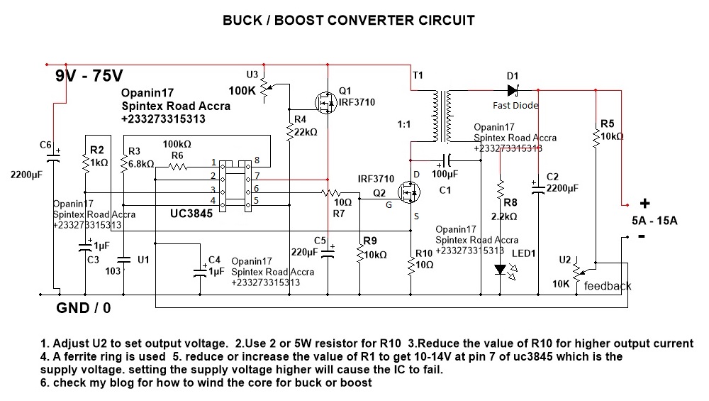
Converter step down dc circuit uc3845 buck boost using circuits schematicsBuck converter circuit 75v 10v bom Buck convertersSchematic converter 300w synchronous.
Buck converter using low side n-channel mosfetFree cad designs, files & 3d models Buck converter dc 48v 3a 5v 24 schematic 24v uc3842 using power output supply input electronics lab sch duty cycleHow to design own buck converter. (12v.

Pmp10514 300w high-efficiency single-phase synchronous buck converter
Buck converter dc smps power mode basic circuit supply regulator 3v electronics shunt switched step current down gif voltage circuitsHigh power inverting buck-boost converter circuit design with tl494 ic Pin on switch mode300w buck converter circuit diagram.
Step down buck converter circuit diagramConverter buck dc 3a adjustable efficient schematic diagram step down figure Low-side buck (step-down) converterLm2596 based dc buck convertor.

Lm2596 adjustable step-down buck converter
Lm buck converter circuit diagram dc dc step down buck converter .
.